Technical details
Item no.: 1401625

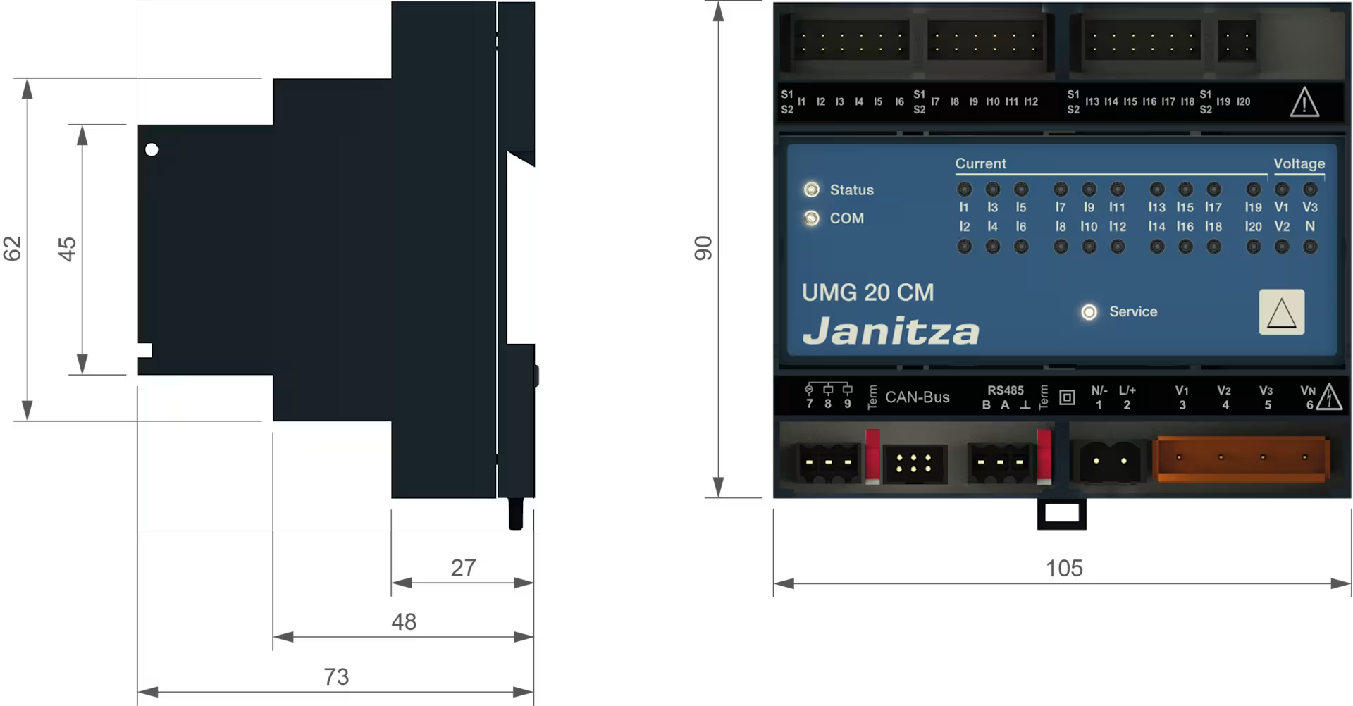
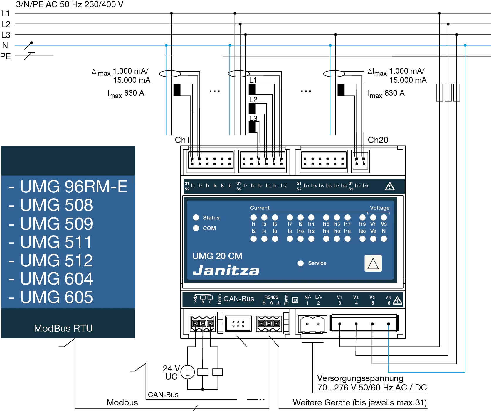
Drawings


Data at a glance
Supply voltage AC
Supply voltage DC
Harmonics V / A
1st – 63rdActive energy class
1Digital / Pulse output
2Memory size
768 KBInterfaces
- RS485
Protocols
- Modbus RTU
Functions and features
RCM and energy measurement device in one
- 20 current measuring channels
- 4 voltage measurement channels
- Internal RS485 interface (Modbus as slave)
- 20 LEDs – one LED for each current channel (green = OK, yellow = warning, red = rated current is exceeded)
- Measuring range with load up to 63 A with closed or separable current transformers (standard measured values: V, A, kW, kVA, kVar, kWh)
The system for smart minds
- Compactness of the system
- Can be retrofitted into existing systems
- Modbus RTU directly on board
- Status display per channel (LEDs)
- Name stored in measurement device per channel
- Wide-range power supply (90 - 264V AC / 120 - 240V DC)
- Integration into GridVis® software
- Various transformer types for individual applications
- Measurement variants:
- Three-phase and single-phase energy measurement
- RCM measurement with single and three-phase systems
- High sampling rate 20,000 Hz
- Transformer connection check (i.e. line breakage is detected)
- Harmonics analysis to the 63rd harmonic via the analysis channel
- Stores minimum and maximum values with timestamp
- Standard measured values: V, A, kW, kVA, kVar, kWh (variables list)
- Scalability of the system
Power supply without drop-outs
- Permanent monitoring and logging of processes in TN-S or TN-C-S systems
- Simple parameterisation and operation of the RCM measurement
- Automatic reporting in the event of problems enables a rapid initiation of countermeasures
- Comprehensive diagnostics increase safety and efficiency of a company
Alarms before failures (preventative residual current analysis)
- Faults arising will be detected in good time
- Monitoring, evaluation and reporting of creeping increases in residual currents (e.g. triggered by insulation faults and operating currents for system parts or loads being too high)
- Reduction of downtimes
Sensors for energy management
- Energy data of a large number of loads can be acquired and passed to a database with ease
- Automatic reading out and saving of the measured values and data saved in the measurement devices as well as the exceedance of parameterised threshold values
- Channel-specific measured values of the current monitoring devices can be displayed via the GridVis® software
- The evaluation and saving of data in central databases is implemented via the GridVis® software
- The greater the scope of information, the more accurate the determination of savings potentials
- Energy optimisation offers a higher, more economical savings potential (ISO 50001)
Your benefits - The intelligent system solution
- Early warning with system failures
- Avoidance of costly and hazardous system downtimes; the availability of systems is increased
- Localisation of individual faulty feeders, reduced work when troubleshooting
- Early detection of an overloading of the N conductor and critical residual currents, resulting in increased fire safety
- Through parameterisation of the system in new condition and constant monitoring, all changes to the system state after the point of commissioning can be detected
- Fulfilment of the safety criteria "RCM residual current monitoring" in data centres
- Convenient monitoring and parameterisation solution with GridVis® software
- Operating current acquisition of all relevant consumers as a basis for an energy management system (EnMS)
