What is a voltage dip?
Voltage dips can lead to major problems, such as the failure of production processes and quality problems. Such dips occur far more often than interruptions. The economic impact of voltage dips is always greatly underestimated.
But what exactly is a voltage dip? How does a voltage dip occur? Can a voltage dip be avoided, or must we try to limit the consequential damage by detecting it in good time? This article discusses these topics in more detail.
According to the European standard EN 50160, a voltage dip is defined as a sudden drop in the effective voltage value to a value between 90% and 1% of the specified value, followed by a direct restoration of this voltage. The duration of the voltage dip is between half a period (10 ms) and one minute.
If the effective value of the voltage does not fall below 90% of the set value, this is considered normal operating status. If the voltage falls below 1% of the set value, this is considered an interruption.
A voltage dip should therefore not be confused with an interruption. An interruption occurs, for example, after a fuse has tripped (typ. 300 ms). The mains power failure is distributed across the rest of the distribution grid in the form of a voltage dip. The figure (Fig. 2) illustrates the difference between a dip, a brief interruption and an undervoltage.


How does a voltage dip occur?
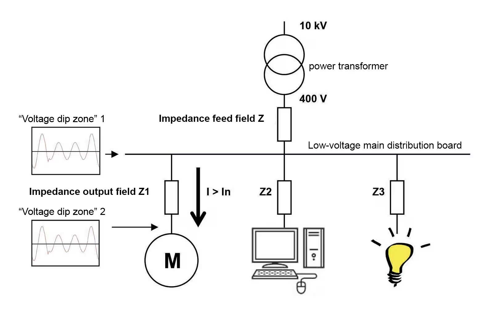
One known cause of small voltage dips is the inrush currents of capacitors, motors or other devices. The figure below shows that the current increases briefly when the motor starts up. The voltage drop across impedances Z and Z1 leads to a slight voltage dip on the low-voltage distributor (dip zone 1) and a slightly larger voltage dip behind impedance Z1 (dip zone 2).
The solution to the problems caused by these dips lies in optimizing the system itself. Switching on devices should not lead to critical voltage dips. For example, a capacitor can be switched on using special capacitor contactors with inrush damping, thereby massively reducing the inrush current.

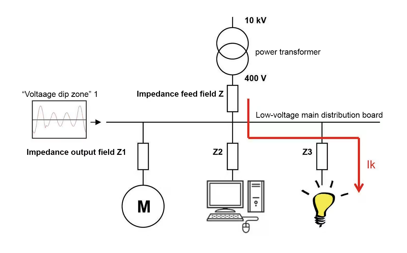
A short-circuit current flows in the event of a short-circuit in the low-voltage network. The amount of the short-circuit current depends on the size of impedances Z and Z3. In practice, impedance Z3 is the highest. The size of impedance Z3 is determined, among other things, by the type and length of the cable. The longer the cable length, the smaller the short-circuit current will be. The short-circuit current causes a voltage drop across impedance Z, causing the voltage at the low-voltage main distribution board to drop briefly (dip zone 1).
In the event of a short circuit, the fuse in group 3 should trip. If this takes 100 ms until the fuse blows, the voltage in the entire system experiences a deep dip for 100 ms.
Short circuits in the low-voltage network do occur, but can often be neglected in practice. Short circuits on the medium-voltage side are more critical.

Dips are most frequently caused in the MV grid. These can be caused by the following influences, for example:
- Earthworks
- Electrical breakdown in a connection sleeve
- Cable aging
- Short circuit in overhead line networks (storm damage, animals, etc.)
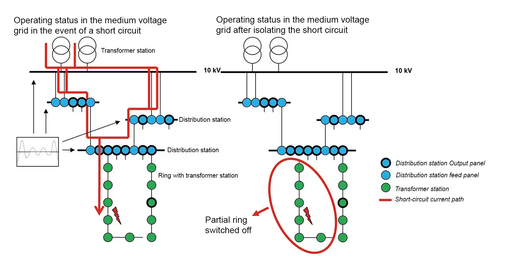
The figure below (Fig. 5) shows a typical example of the structure of a MV grid. The known transformer houses / distribution substations (green dots) are interconnected in a ring and connected to a distribution station (blue dots). The ring is always open somewhere (see ring in the green dots at the bottom right). If a short circuit occurs, a short-circuit current flows (red line). This flows until the fuse in the distribution station switches off the ring. This can be seen in the figure on the left (top left in the ring).
This means that a high current flows briefly during the short circuit. Due to the grid impedances, this leads to a brief drop in voltage across the entire network. This brief drop in voltage is experienced as a "voltage dip".
About 75% of voltage dips are caused in the medium voltage network. Often, these cannot be avoided by consumers.
Short circuits in the high-voltage network Short circuits in the high-voltage network are often caused by thunderstorms or (faulty) switching operations. The latter especially in areas at the end of a high-voltage line.
Problems due to voltage dips
Voltage dips can lead to the failure of computer systems, PLC systems, relays, and frequency converters. In critical processes, even a single voltage dip can result in high costs, and continuous processes are particularly affected by this. Examples include injection molding processes, extrusion processes, printing processes, or the processing of foodstuffs such as milk, beer, or soft drinks.
The costs of a voltage dip consist of:
- Lost profits due to production downtime
- Costs for making up for lost production
- Costs for late delivery of products
- Costs for lost raw materials
- Costs for damage to machines, devices, and molds
- Maintenance and personnel costs
The average costs of a voltage dip depend heavily on the sector:
- Fine chemicals €190,000
- Microprocessors €100,000
- Metal processing €35,000
- Textiles €20,000
- Food €18,000
Sometimes processes take place in unmanned areas where voltage dips are not noticed immediately. In this case, for example, an injection molding machine can come to a standstill unnoticed. If this is discovered later, major damage has already been done. Customers receive the products too late and the plastic in the machine has hardened. In print shops or in the paper industry, paper can tear or even cause a fire. Another well-known example is the damage caused to tire manufacturer Vredestein by voltage dips.

Susceptibility of IT systems to voltage dips and interruptions
IT systems in particular are susceptible to voltage interruptions and voltage dips. This means that all processes controlled by microprocessors are susceptible to such disturbances, for example
- PLC systems
- Frequency converters
- Machine controllers
- Servers, PCs, etc.
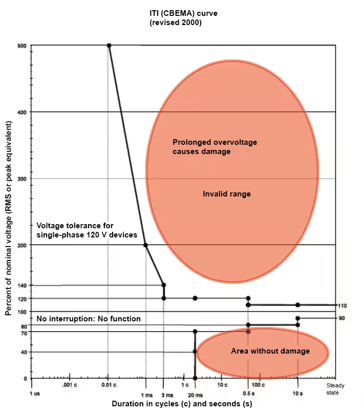
The ITI-CBEMA curve drawn up by the Information Technology Industry Council defines when a voltage dip leads to the failure of IT devices and when a voltage spike causes damage to IT devices. Although the model was developed for 120 V–60 Hz networks, it is also used for devices connected to 230 V–50 Hz networks. The model can be used by manufacturers as a design guideline.

How can you counteract voltage dips?
Voltage dips due to inrush currents can be avoided by improving the design of the technical system. Voltage dips caused by short circuits in the low-voltage network are normally rare. Most voltage dips are caused by short circuits in the MV grid. Nothing can be done about the causes of these dips.
The dips themselves can be remedied by:
- Static UPS, a DC voltage source with a downstream inverter. This solution is often used as a bridge to the emergency generator.
- Flywheel continuously moving with the load (dynamic UPS). In the event of a brief interruption or a dip, energy is drawn from the flywheel. This solution is not cheap and is often used in data centers.
- Connecting control and regulation systems for a process to a stabilized power supply.
- Retrofitting the electrical infrastructure. This is not always possible and certainly not cheap.
From this we can conclude that eliminating voltage dips is not a cheap affair. It can sometimes be effective to signal voltage dips at an early stage. With good reporting tools, the causes can be identified and more targeted (and therefore more cost-effective) measures can be taken.
Signaling of voltage dips
Janitza offers a wide range of analyzers that are capable of detecting short interruptions and voltage dips. The UMG 604 network analyzer continuously monitors more than 800 electrical parameters. All channels are scanned 20,000 times per second, signaling and registering brief voltage interruptions and dips. An e-mail or SMS can then be sent on the basis of these events. Detailed reports can be generated using the GridVis® Basic software package included in the scope of delivery.
By arranging the UMG 604 in the infeed field, you have a comprehensive and cost-effective solution for detecting, recording, alerting and reporting voltage dips. The measurement device is equipped with a web browser, which makes it possible to call up the most important parameters directly from the measurement devices with little effort and without complicated software programs. The built-in event browser can be used to analyze interruptions and voltage dips and process them into reports.
The Janitza measurement devices for detecting brief interruptions are:
- UMG 604, a compact network analyzer for DIN rail mounting
- UMG 509, a network analyzer with intuitive color screen for panel mounting
- UMG 605, a class S power quality analyzer for DIN rail mounting
- UMG 512, a class A power quality analyzer with color screen for panel mounting
The GridVis® basic license (GridVis® Basic) is supplied free of charge together with Janitza measurement devices. This packages allows users to
- read out realtime measured values,
- retrieve historical measurement data in files and graphics,
- analyze short-term interruptions, transients, and voltage dips,
- print out complete EN 50160 reports "at the touch of a button" and
- generate simple good/error reports.
With the built-in report generator, it is possible to process even periodic voltage dips, short interruptions and voltage peaks into clear reports using the ITI curve (CBEMA).
The figure below (Fig. 10) shows that three voltage dips occurred, which led to the failure of one system.


Summary
Voltage dips occur relatively frequently and are not always recognized. The economic damage caused by voltage dips is greater than that caused by interruptions. A number of voltage dips can be reduced by retrofitting the electrical infrastructure. The use of uninterruptible power supplies or choke coils can limit the consequences of voltage dips. In some cases, however, these measures are too expensive. The first step is always to detect and document voltage dips. Janitza offers complete solutions that continuously monitor and analyze entire operating processes sustainably and reliably. With the use of modern measurement technology, power quality problems can be identified and rectified in good time. An increase in supply reliability is guaranteed, maintenance costs are reduced, and the service life of the production system is extended.
Source data
VOLTAGE SAGS AN EXPLANATION CAUSES, EFFECTS AND CORRECTION Ian K.P. Ross, MIEE
POWER QUALITY, OVER SPANNING STROOM EN HUN INTERACTIE Dr.ir. J.F.G. Cobben & Ir. J.N. Luttjehuizen
